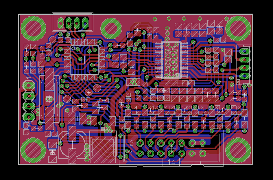
Small but flexible intelligent stand alone stepper motor controller.
This product was made for a motor company.
They had a programmable and independent motor controller that was to expensive and with low flexibility. So they asked me if a could do a better and cheaper version. It was a challenge to build it so small with that much motor power .
The upper board is my first Beta version. The lower one is the motor board that i should replace. It´s main features is “small but flexible intelligent stepper motor controller”.
Main Features
- 8 Inputs with programmable functions.
- 2 Outputs with programmable functions.
- 2 Amp Stepper Driver , Selectable in 20 steps from 100mA to 2000mA. 12 – 30 VDC Input voltage.
- Current Standby, Both Time before standby and current is programmable.
- 2 Analog inputs with programmable functions.
- 1/1 , 1/2 , 1/4 , 1/16 microstep is selectable by input or internal state.
- Programmable functions is set by a PC application.
- FW update can be made by customer (done in the PC application).
- Programmable Acceleration/Deceleration Time.
- Smooth motor motion in manual step mode.
Programmable Input Features
- Go To Home “Position zero”
- Step continuously at given direction
- Step xx steps at given direction
- Direction Step continuously at positive direction
- Step continuously at negative direction
- Step xx steps at positive direction
- Step xx steps at negative direction
- Positive end sensor input
- Negative end sensor input
- 2 Inputs for speed, 4 programmable speed settings
- 2 Inputs for current, 4 programmable current settings
- 2 Inputs for microstep, 4 programmable microstep settings
- Emergency Stop, 3 different variations ( Pause ongoing function ) ( Pause and Exit all ongoing functions) ( Pause and Exit all ongoing functions and release current to motor )
- Emergency Reset Wait until, trigged functions is memorized and on hold until this function triggers Current standby, Releases current to motor
- Abort if, abort all functions when trigged
Input Features
- High signal in, between 4.5 to 30v is acceptable for a logic 1 (levels can be changed)
- Pull up signal can be applied to input, if pull up is enable, the input pin only needs to be grounded to trigger input function
- Functions can be set to trigger on negative “falling signal” or positive “rising signal”
Output Features
- Both outputs can handle up to 300mA current each.
- Outputs can be set to positive or negative response out
Programmable Output Features
- Busy, Triggers output when device is busy or motor is running
- Home, when current position is zero “Home” can be set with a +- tolerance
- Positive, Negative, Or both end sensor. Activates output on end sensor trigger.
The final version. The board dimensions is 30 x 37 mm
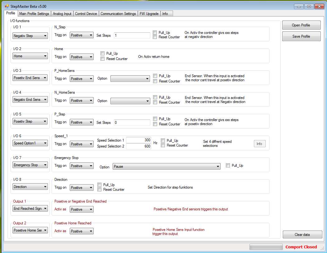
I created a PC program in C# that makes the board profile really easy to setup.
Profile
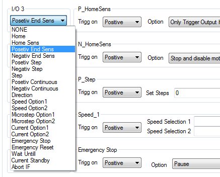
Input options
Every input / output on the motor board can be set to a selected function.
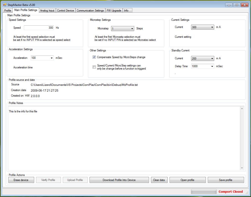
Main profile settings
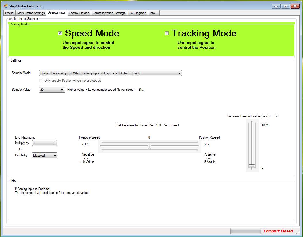
Analog Input Settings
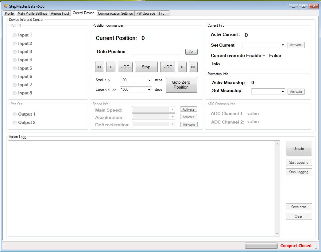
Device Control
Manual control of the motor.
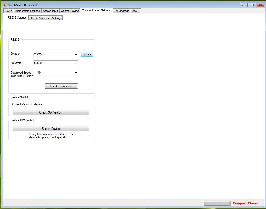
Communication settings
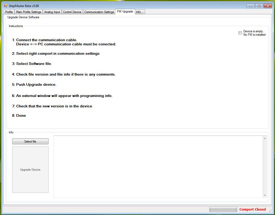
Firmware Update
Built in firmware update function for easy upgrade.


