

By request for an irrigation system based on “Ebb and Flood irrigation technique” I made a system that should be able to handle a very large area and variation in complexity as well as irrigation types. The system is modular and is based on a main unit and multiple modules that are used for sensors and system control. My idea was to make the system stand alone so there should be no need for a computer running the garden/greenhouse, but I still wanted a good and easy way to configure and log the system. So with that in mind I built a system that is stand alone, but configured with a PC program trough radio/USB.
This is what I came up with:
PC software
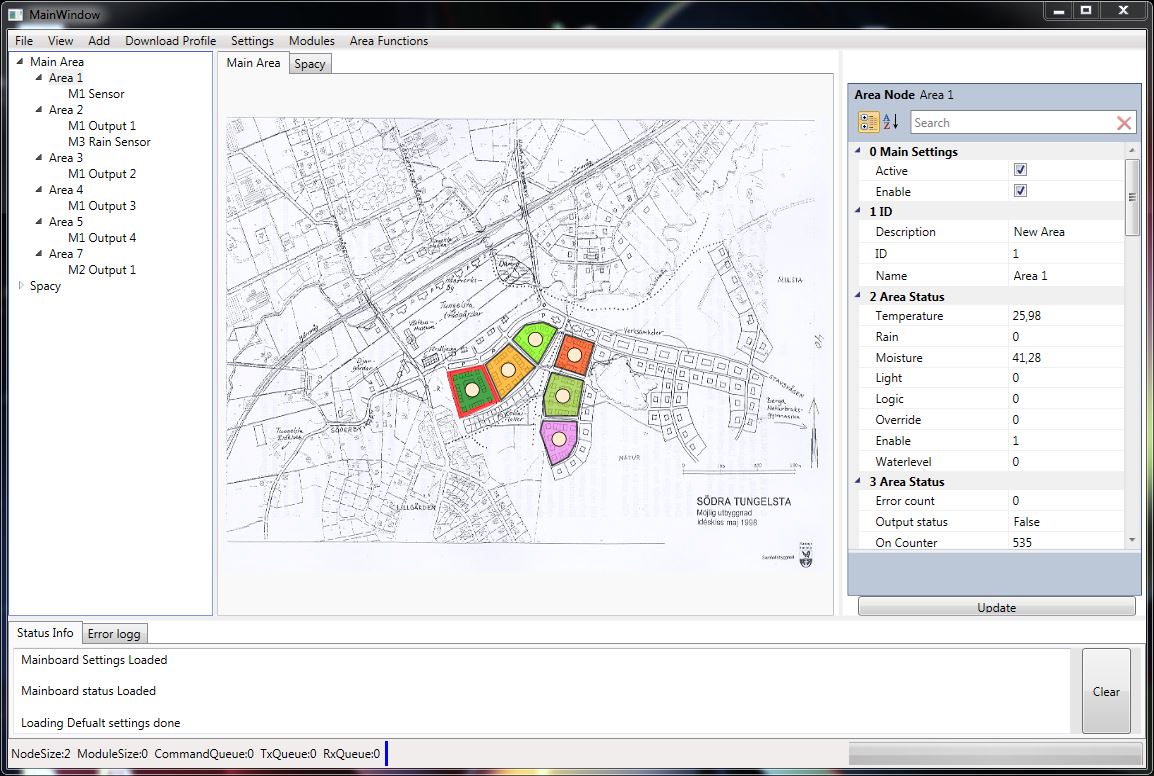
I though about how to make it easy to see the setup ether if it’s a small garden or a large greenhouse. So I made an aerial view solution. You can add as many “views” as you like and they will show up as tabs (blue arrow). With each view you can add a picture that should show your garden/greenhouse layout or parts of it by using multiple views. Then you can freely draw smaller boxes on the picture that indicate specific areas. Each box can be the area the sprinkler is affecting if you use sprinklers. Or it can be a flower bed area that use water drop irrigation. And so on. One module can control one area but it can also share sensor information or status with other modules/areas.
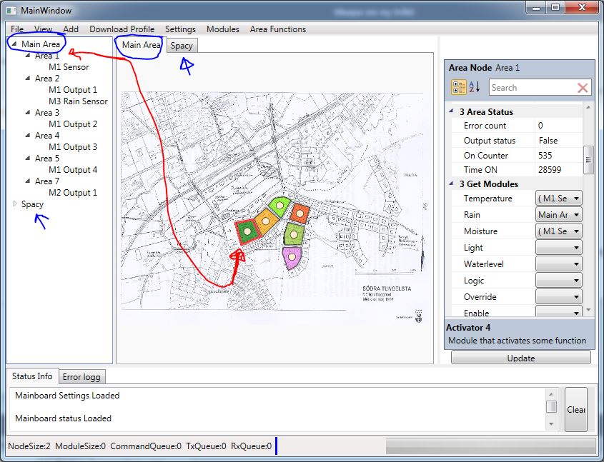
Blue is views and red is areas within that view.

Each area can connect to sensors or signals from the whole system.
Only sensors that can be used (in this case Rain sensors) will show in the drop down selection box.
Each area can control up to four activators, either on it’s own area or others. For example one main water solenoids that supplies all areas can be set in each area output, so when the area sprinkler solenoid is turned on the main water solenoid only supplies water when it is needed.
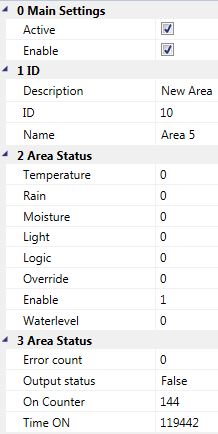
Area Status holds current status from the area (Sampled from the selected sensors).
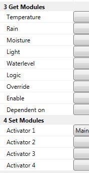
Get Modules is where I select a specific module that holds a wanted sensor. Only modules that have the selected sensor will show in the list.
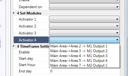
Set Modules is where I select activators that should be enabled if the selected area output is active.
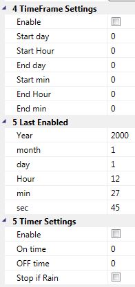
Time frame Settings is where you can set start and end time for each day or for a specific day when the profile should be active.
Last Enable is exactly what it says – the last time the area activators were enabled.
Timer Settings is where you can set a “dumb” timer.
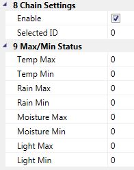
Chain Settings is where you can link the selected are to another area, so this area follows the selected area’s profile.
Max/Min Status holds the maximum and minimum recorded Temp,Rain,Moisture an Light values.
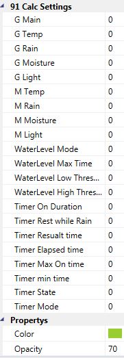
Calc Settings are only for the irrigation profile for this area. The window below sets this.
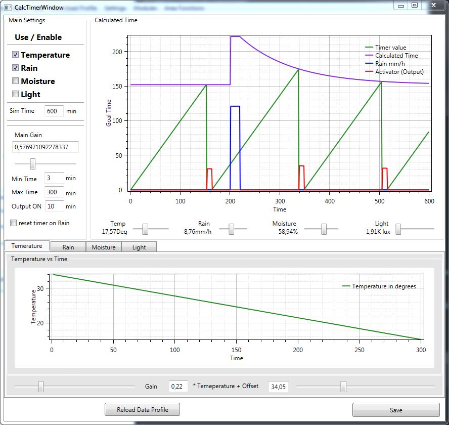
I have been experimenting with different Irrigation profiles and have implemented one that enables various settings. The “Calculated Time” box enables you to test various weather scenarios. If the area has Temp,Rain,Soil moisture or Light Sensors linked or only one sensor, this profile can calculate the Irrigations.
The values in the picture are not for a real profile, they are just for show.
Main Unit
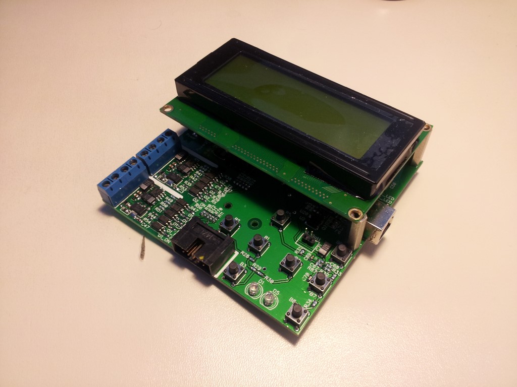
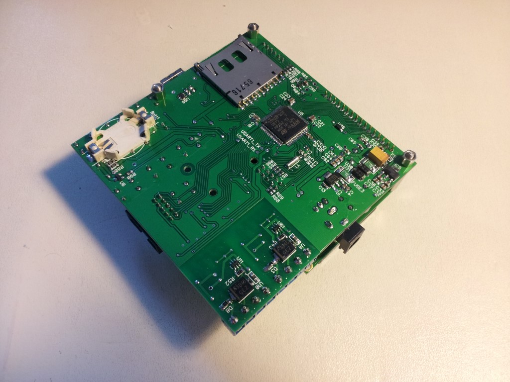
The main unit is based on a STM32F103 32-bit MCU. It is connects to the modules by two opto-isolated RS485 networks. There is one radio port that can be used if a wider range is needed. This is done with wireless routers that extend the RS485 network. The Main unit only needs a computer during the setup, but if the user wants a displayed overview (almost) in real time the computer can log and display the current status of the system. The main unit connects to the computer trough USB or Bluetooth.

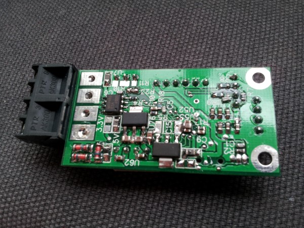
I have made one water level sensor board that can control one water solenoid. This one is specifically made for the “Ebb and Flood irrigation technique”. It is based on capacitive sensor technique so the PCB do not need direct contact with the water.
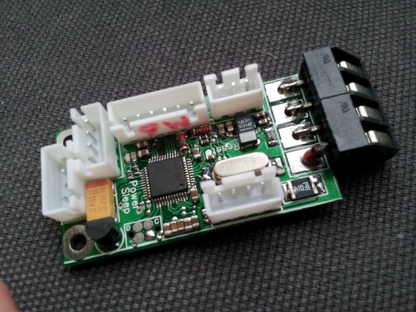
This is my standard board that I can connect to moisture, light, logic, analog and rain sensors. It has an internal temp sensor but the module can connect to external temp sensor with higher precision if needed. The board also contains four output signals for activators like water solenoids. The module is powered trough the RS485 network and uses sleep modes to reduce power consumption. The plan is to integrate a bootloader so that each module can be upgraded from the main unit.
More module versions will be create. They can be used for various functions in the system.
For example
- Motor controller for fans and venting hatches.
- Water nutrient concentration sensor.
- Wall mounted buttons and information displays.
- And more …
Communication between the main unit and the modules is done trough a RS485 network with 32-bit address space. It uses data packages with CRC and ACK / resend functionality to ensure that right data is sent and received by the right module.
The main unit can scan the network and request each module’s ID that is connected and responding. The modules and main unit restart if they by any chance happen to hang. The main unit can send a restart command trough the network if it detects a continuous error respond from any module. This is mostly not a problem, but if it by any chance should be, the main unit has the ability to reset the network.
Simple video in Swedish
More to come later on..